|
For fifth-wheels and other types of tow trailers, 12v power is supplied to your rig while on
the road via what is called an umbilical cord (abbv. u/c). The cord plugs into the
truck's female receptacle on one end. The other end is fans out to various exterior lights (stop, brake, turn) and
also supplies power to your emergency brake control, if you have one.
|
|

|
| ☞ | |
You won't be able to pull your trailer at night without a u/c, since that's what
powers the external lights on your rig. And even worse, you won't be able to control the
automatic brakes on a big rig without one.
|
| ☞ | |
Occasionally remove the cover from the u/c box and check the connections. Bumpy roads can shake
the wire nuts loose from the wires, yielding separated connections. This happened to us on the rough roads
of Canada; I was lucky to find it or some bad things could have happened!
|
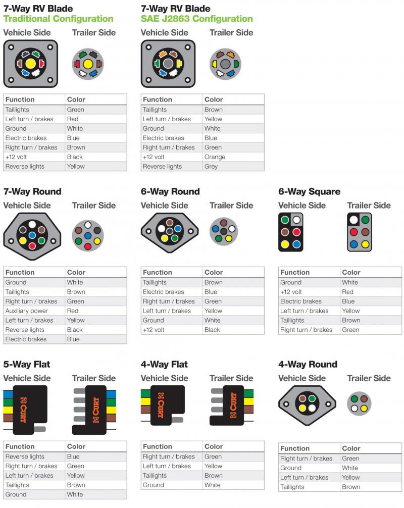
Umbilical cords come in 4-way, 5-way, 6-way and 7-way configurations. The "way-ness" refers to the number of wires.
You'll also see a 7-way called a 7-pole, 7-pin, 7-blade or 7-wire connector.
Here is an image showing the various types.
|
|
[click to enlarge]
|
The u/c cord on our fifth-wheel is a 7-way.
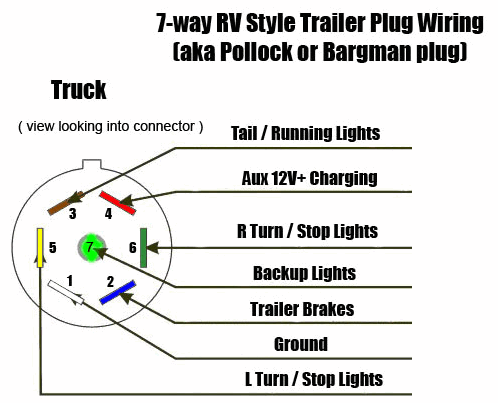
Here is what the 7-way wiring looks like on our rig.

| |
[click to enlarge]
|
| |
| |
[click to enlarge]
|
|
Also see here
for more info on 7-way umbilical cords.
If you have a 4-way connector then there won't be a lead to help keep your battery charged
while driving. If you are on the handy side, you can wire your 4-way
to maintain battery power.
See here.
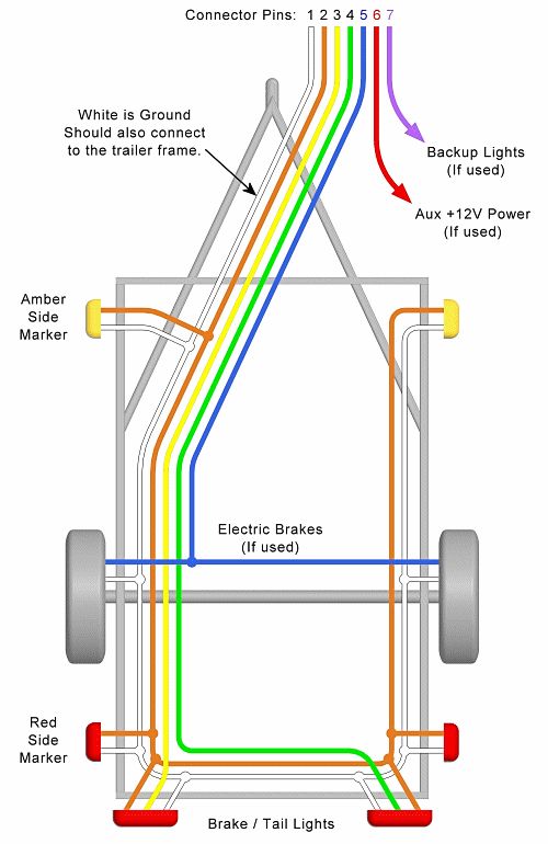
Here is a diagram of how 7-way might be distributed through your rig.
|
|
[click to enlarge]
|
| ☞ | |
There are no standard wire colors; it's completely up to the manufacturer of the cord and
receptacle.
It also depends very much on how your friendly mechanic wired it up to the
various lights and thingys on your truck.
I have found almost every possible variation of wire colors on the 'net, and my particular
wiring doesn't conform to any of them.
So be aware that your wiring may be different than whatever you find on the 'net.
Bottom line is that if you have to redo your wiring,
do it by logical function (see the technique below) and don't depend on any particular color scheme.
|
| ☞ | |
I would advise that you remove the cover from the cord box and write down how the various colored wires
are connected. This could prove invaluable should you have connection problems on the road, like ripping
the umbilical cord out of the box! Keep your wiring diagram in your rig.
|
It is crucial that your u/c is functioning properly, for a couple reasons. First, power to your
rig's exterior brake lights and turn signals is supplied by the cord. Secondly and most importantly,
your rig's brake system gets its juice from the cord. No 12v, no stopping! It is very important that you check
out the exterior lights after you hook up but before you take off. It is convenient to have someone stand
in the rear and let you know if everything is working, but you can easily walk back and forth to check it out yourself.
Your in-cab brake control system will likely let you know if the connection is faulty. Mine doesn't show any
numbers on the display unless the u/c is correctly connected. This might also be a good opportunity to
set the control's pressure value to an open road setting.
| ☞ | |
After you connect your u/c and before you head out, pull the rig for a few hundred yards and then tap
on the brakes. See if the trailer's automatic braking is to your expectatiion. If it is jerky then you need to
back your in-cab controller off a bit. If it's sluggish then move it up. You don't want to be annoyed by poor
braking while on the road.
|
Should you find yourself in the embarassing position of having pulled away from the trailer with the unbilical
cord still attached, you may be able to rewire it. Here is a
Youtube video that shows you how.
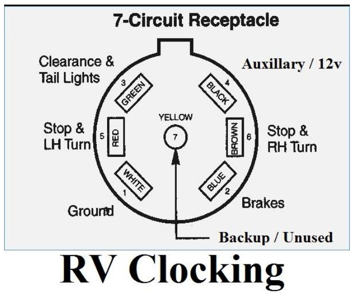
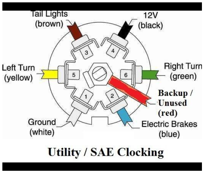
The diagrams below show two different wiring standards for 7-way plugs. The one on the left is used for RVs like
fifth-wheels. Umbilical cord and socket manufacturers adhere to the RV standard for pin position and wire colors.
Although pin numbers are shown in the diagrams, I do not believe that they are standard. Rather, people like
myself prefer to refer to a pin's position relative to the face of a clock. For example, in both diagrams the
white ground wire is at the 7 o'clock position while the black 12v wire is at 1 o'clock. This terminology
is referred to as "clocking".
| |
[click to enlarge]
|
| |
| |
[click to enlarge]
|
|

| |
It's important that you know how your umbilical cord is wired up to your trailer. You can probably go for quite
a while without this knowledge, but eventually something's going to break. What would you do if you accidently
pulled away from the rig without first unplugging the u/c? Now you have a mess. You probably think you can just
join all the wires together, red to red, blue to blue, etc. Well, if your rig's anything like mine I can almost
guarantee that the colors won't match up. So here we're going to prepare you for any u/c eventuality. After we're done
you will know where all the external rig wiring goes and how they are connected to the u/c.
Before you begin, I recommend you make a drawing of your truck's 7-way receptacle, like the one
shown above. It will likely be mounted
on the rear bumper or inside the truck bed. On this drawing you will be showing the seven
pins and the function of each. You don't have to number them. As you detect what each pin is used for,
make a note. Keep the drawing with you in your rig.
First, let's find out what each pin on your u/c outlet does and also verify that the outlet obeys the
RV standard shown above. If not, it may be SAE standard wiring, in which case the colors red and yellow will be
swapped, as will green and brown.
You'll need a multimeter, one which has at least a voltmeter and ohmmeter. A cheap one will do fine.
| | 
|
Turn off the truck ignition and unplug the u/c.
First, let's see which pin is ground. You might logically think it would be the center pin, but it probably isn't.
For sockets obeying the RV standard it will be the white wire at the 7:00 o'clock position.
Since the ground wire is connected to the frame of the truck,
there won't be any current flowing between the chassis and the ground wire.
So we're going to use the ohmmeter part of the multimeter. An ohmmeter measures the resistance in a wire,
in ohms (who would have guessed?). When you touch the two meter leads together you will see the readout drop
to zero, indicating a lack of resistance. When you touch one lead to the chassis and the other to the ground
wire you should see the same thing, except maybe it won't go all the way to zero since the metal chassis does
have some resistance, as does any metal.
If you find that the pin at the 7 o'clock socket position is in fact ground, then great. Otherwise something
is amiss. Either the wire is broken or disconnected from the chassis, or ground is found on some other pin.
Use your ohmmeter to check the other six pins to see which one is actually the ground. If you find it,
make a note of the proper pin on your diagram.
A human interest story: When I did this it turned out my ground wire wasn't grounded at all
☹. It had shook loose on some very bumpy roads in Canada.
Having a ground connection is critical for your u/c to function, so how did my u/c make a ground connection
without the white wire connected?
Apparently the whole grounding thing depended on
the frame of my trailer resting on the fifth-wheel hitch to establish a mechanical ground connection
between truck and trailer. That's scary! Guess God's been looking out for this old redneck boy after all.
Ok, back to work. Now that you've found the ground wire, let's use the voltmeter portion of the multimeter
to verify the other pins. First, put the red (+) lead on the 1 o'clock pin and the black (-) lead on the
ground pin. This is the "hot" lead so you should be getting a reading of 12v or so. If not, then you need to
go searching the other pins for it. When you've found it, write the pin position on your diagram.
The hot lead is sometimes referred to as the "ext" lead. It is used to supply juice to your rig's external lights,
like the turn signals, stop lights, flashers and running lights. It also maintains a charge on your house
battery while driving.
Now that you've isolated the ground and hot wires, turn on the ignition and turn on the left turn signal.
Use the voltmeter to determine which of the socket pins is fed by the turn signal. It should be the pin at
the 9 o'clock position.
Put the voltmeter's black lead to ground and verify that this is indeed the correct pin.
Since the turn signal blinks on and off, the needle on the voltmeter will move back and forth
accordingly, so leave the lead touching each pin for a few seconds.
If this isn't the right pin, keep moving the red lead to different pins until
you get a reading. When you find the correct pin, make a note of it on your diagram.
Do the same procedure for right turn signal (3 o'clock) and tail lights (11 o'clock). Note that the pins for the
left and right turn signals should also control the emergency flashers.
To find the wire that controls the brake lights (probably at 5 o'clock)
you'll have to have someone push on the truck brake pedal while you
visit the remaining wires.
This wire probably also controls the automatic brakes on your rig.
If your hookup is like mine, there will be no backup lights connection (center pin, yellow wire).
If not, it is possible to repurpose
this wire for other uses, if desired; something like a rear camera comes to mind.
-- https://www.rvupgradestore.com/Choosing-the-right-connectors-for-your-trailer-wiring-a/330.htm
-- https://www.etrailer.com/Trailer-Breakaway-Kit/Tekonsha/2028.html
-- https://www.etrailer.com/faq-wiring.aspx
Ok, congratulations. You now know what each of the seven pins in your 7-way does, and you've made a diagram
for future reference. The next step is to
match each pin on the plug with its associated colored wire at the other end.
With the u/c unplugged from the truck, use your ammeter to find these associations. Put one lead of the meter
onto one of the plug pins and then put the other lead to each colored wire until you get a zero (or low)
reading. Write down the pin-color match on your diagram. Do this for all seven pins. Note: when measuring
resistances it doesn't matter which lead you place where, as there is no current flow.
Note that pin positions are the mirror image for plug and socket. For example, the socket pin at 9 o'clock corresponds
to the pin at 3 o'clock on the plug (looking directly at the plug). Likewise, socket position 5 o'clock is plug
position 7 o'clcok.
Once you have determined the color codes for all functions, plug the umbilical cord back into the truck socket
and repeat
the above procedure, this time testing the voltages on each of the wires at the end of the umbilical cord.
This serves as a sanity check to ensure you have the correct designations from the truck socket all the way back
to the colored wires at the end of the u/c. Your diagram is almost complete.
The colored wires at the end of the u/c
probably collect inside a protective metal box. Open up the box and find the ground (white) wire. You might have
to run a wire from the truck's frame to make testing within reach. From then on
it should be easy to determine the other wires purposes, by testing for voltages between the wires and the
ground wire.
The final step in completing your diagram is to make a note of the wire colors leading from the u/c back to the rig.
Unlike the u/c these colors aren't likely to conform to any standard.
Don't forget to put the cover back on the box when done.
|
When you're done with the above procedure you will have a nice handy-dandy wiring diagram of your rig's exterior
lights and brakes, along with which u/c wire and pin services each.
BTW If your u/c wiring color codes doesn't match either of the standards show earlier, don't panic. It must
means that some bozo wired it wrong, but as long as the lights and brakes function correctly then you're good.
This is why you make diagrams!.
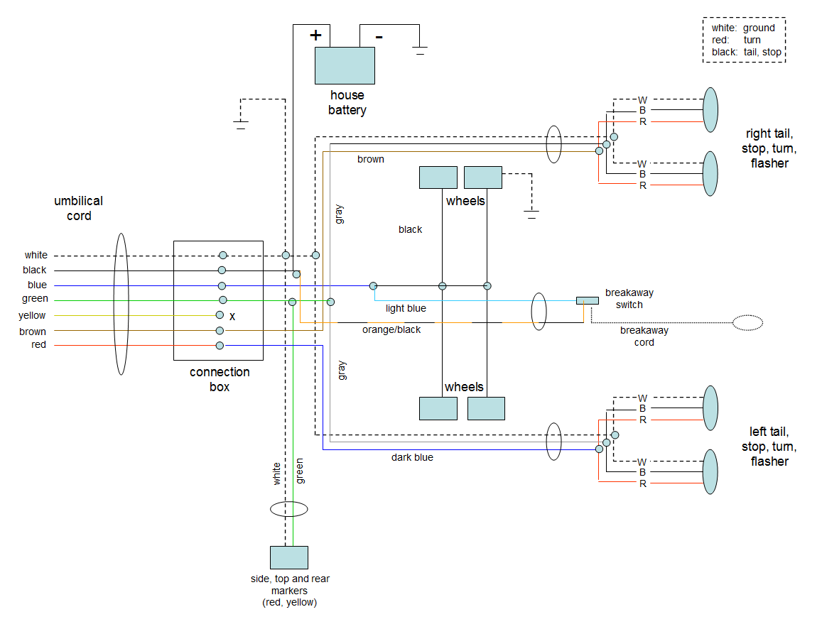
Here is how our particular fifth-wheel is wired. It took hours of chasing down wires, sometimes on my
back, but I got it figured out. The internal wiring in your rig may have different color coded wires,
but the overall layout should be basically the same.
|
|
[click to enlarge]
|
Notice in the above diagram that the breakaway switch power is provided by the black (12v) lead of the
umbilical cord rather than the house battery. This ensures that the emergency breaks will be activated regardless of
whether or not the house battery has charge. So if the pin should be yanked out of the breakaway switch,
power will flow through the black lead to the black/orange lead, through the breakaway box
to the light blue lead and then on to the black lines leading to the breaks.
Here is the RV standard information presented in a tabular form

|
|
[click to enlarge]
|
I have left the last two columns blank so you can jot down the wire colors that lead to the female
receptacle on your tow vehicle, as well as the colors that connect to the end of the umbilical cord inside
the connection box on your trailer.
| ☞ | |
You could use the yellow reverse/aux wire as an auxillary power source while connected to the tow vehicle.
For example, it could be used to power some 12v lights or other small 12v appliances.
|
I carry a replacement umbilical cord and receptacle with me, one because they are relatively cheap,
and two because yanking one out of the
truck or trailer may cause more damage than can be repaired.
Here is the cord we have, and
here is a corresponding truck receptacle. Make sure whatever you order matches your rig.
Contrary to popular legend, the standard 7-way wiring connecting your trailer to the tow vehicle does not
provide sufficient current to charge the house battery.
The black (ext) wire on the 7-way connects to the positive post of the rig's battery, and essentially connects
the vehicle and house batteries in parallel, sort of like how jumper
cables work. So you might think that recharging of the house batter would occur but it doesn't. The current
flowing through this circuit is not much, primarily because the ext wire is of small gauge.
All this really does is give the battery a little assist. It isn't
enough to actually charge the battery.
Voltages
-- can't find anywhere on internet
-- don't need key on for 12v
-- truck running: 12+ v
Maintenance
Umbilical cords shouldn't require much in the way of maintenance. Just give it a quick check well before you set
out so you can address any problems that might turn up. Have someone stand at the back and tell you if all is ok as
you try the headlights, turn signals, flashers and brake lights. If a problem turns up, look at the section on
Troubleshooting below.
| ☞ | |
Do you carry spare light bulbs and lens covers for your rig's exterior lights?
|
Open up the umbilical cord's connection box where the cord connects to the rig's wiring. Connections are probably
done with electrical wire nuts. Inspect the connections to see if any of the nuts or missing and, if so, replace
them. Also make sure that they are tight. If you're handy with a soldering gun you can mechanically reinforce
wire connections by soldering them together. Be sure to us a wire nut to keep wires from touching.
| ☞ | |
While the connection box is open, it would be a good time to jot down which of the umbilical cord colored wires
are connected to which colored wires on your rig.
|
Corrosion can occur on any exposed electrical connection. This is especially true when travelling in locations
with road salt. Corrosion-causing moisture can be slowed down or prevented by spreading a little diaelectric grease on the pins
of a connector before plugging it in.
Here are some on Amazon.
We use
Ultra-Seal.

|
|
[click to enlarge]
|
| ☞ | |
Note that it's also a good idea to rub a little electrical grease on the battery connections of your vehicle
and house 12v batteries.
|
Troubleshooting
There are a number of ways that an umbilical cord can stop working. If all of the functions are disabled, it is
likely that the cord has come unplugged. This should be easy to check; just push the plug into the socket and wiggle
it a bit. If one or two functions are disabled (ie, brake lights
not working) then the problem can be a little harder to find. Here are the steps to take to chase down the problem.
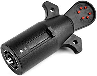
First of all, do yourself a big favor and get a socket tester. Here is an example of a 7-way female receptacle
tester
available on Amazon
. I use the
Mictuning but most any should do fine (check their ratings). The beauty of this type of tester is that all you have to do is plug it directly into
your 7-way socket and look at the lights. For example, with the ignition on, turn on your left turn signal and the
appropriate light on the tester should illuminate. Same for the right signal, brake lights, running lights and
backup lights.
|
|
[click to enlarge]
|
Amazon also has similar testers for other connector types like 4-way or 6-way.
Don't forget that u/c problems can be caused by faulty wiring in your tow vehicle. To check this you'll have
to crawl up under the tow and look at the wiring going to the u/c. If you don't see anything suspicious then
you need to check voltages at the 7-way pins (see table above).